Quality and testing
1. Quality assurance
Each batch is logged during the manufacturing process. In the final testing the production of the components is tested according to the details in the catalogue.
1.1 Control measures
The incoming inspection of the materials and the final testing of the batches are in progress according to defined test criteria and quality standards.
1.2 Qualifications
The qualification tests and reliability data are exported to the requirements of each applicable Requirement and monitored by the parent bodies.
2. Applicable rules
- DIN 40040 classes of applications and reliability data for electronic components.
- DIN 40046 environmental testing for electrical engineering.
- DIN 40,081 and periodic batch-wise guide to the reliability tests.
- VDE 560 rules for mica capacitors for the UN to Part 19 Urms to 500V and 3000V.
- GfW A0200 control system and production control for production of materials and components, high reliability.
- GfW A0300 procedures for the qualification of components.
- GfW A0900 X-ray inspection of electronic components.
- CM 100 Group GfW provision Mica Capacitors
- GfW CM 101 to 104 individual rules CMR04 and CMR07 Type.
- IEC 384-1 Fixed basic standard terminology and test methods.
- IEC 384-5 standard for mica type capacitors for nominal DC voltage up to 3000V.
- IEC 68 climatic and mechanical test methods for components.
- CECC 00100 Basic Provisions.
- CECC 30,000 Harmonized Gütebestätigungssystem for fixed capacitors.
- MIL-C-5 design standards for mica capacitors
- MIL-C-5/18 axial and radial lines.
- MIL-C-39001 detail specification for mica capacitors with confirmed reliability.
- MIL-STD-105 test attribute Statistical Quality Control.
- MIL-STD-690 Sichprobenverfahren to prove the reliability.
- MIL-STD-202 test methods for electronic components.
- CCTU 01-01 Mechanical and climatic test methods.
- Electrical test methods CCTU 01-10.
- BS 9070 requirement for fixed capacitors.
- Section 7 General information and methods of mica capacitors.
- BS 9070 mica capacitors, metallized, rectangular.
- N002 up to 005 individual standards.
- VG 95,210 test electronic components, climatic, mechanical and electrical tests.
- VG 95,211 test patterns, pattern approval and quality assurance.
- VG 95,212 lists of approved devices.
- Fixed Part 7 (LZB).
- VG 95,083 Statistical Quality Control, Attribute test.
- VG 95,296 fixed, basic legislation.
- VG 95,296 Glimmrkondensatoren.
- Part 7 Technical values and Inspection.
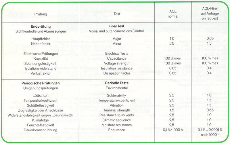
3. Final inspection by AQL
Each capacitor is measured in terms of capacity and dielectric strength. Insulation resistance, dissipation factor and temperature coefficient are tested by sampling. Capacitance, sustaining voltage strability and the climatical and mechanical tests are part of the sampling or alternate test of the type approval test.
4. Reliability of information / failure rates
In order to fall below the failure rate under special conditions capacitors are periodical took out of the production and tested under agrravate conditions.
MIL-C-39001, Table VII
Sampling to confirm the failure rate.

5. Verification
The data for measurements and tests for capacitance, loss-factor, withstanding voltage, insulation resistance and dimensions are noted in the specification of the several types.
5.1 Solderability
Solder bath method, terms according to IEC 68-2-20 Ta or MIL-STD-202, method 208, immersion depth until 2 +0.5 / -0 mm of the body with heat shield. Requirement: Good tinning through all-over surface.
5.2 Resistance to soldering heat
Condition according to IEC 68-2-20 Tb, method 1, depth to 6 +0.5 / -0 mm from the body. Requirements: No Damage Cap change = <0.5%.
5.3 Terminal Strength
Tensile stress Ua 1 IEC 68-2-21 and MIL-STD-202, method 211 A. tension 5N, 10N, 20N. Bender test Ub IEC 68-2-21, method 2, requirements: undamaged.
5.4 Wings
Condition according to IEC 68-2-6 Fc. Method B4, 0.75 mm or 10 g, frequency ranges: 10 to 55 Hz - 10 to 500 Hz - 10 to 2000 Hz duration of 6 h as per MIL-STD-202, Method 204, Test Condition C. Request: no interruption.
5.5 Resistance to Solvents
Conditions according to MIL-STD-202, Method 215. Solvent: 1 Vol T + 3 bµ volume isopropyl alcohol + 3 vol. T. spirit. requirement: undamaged.
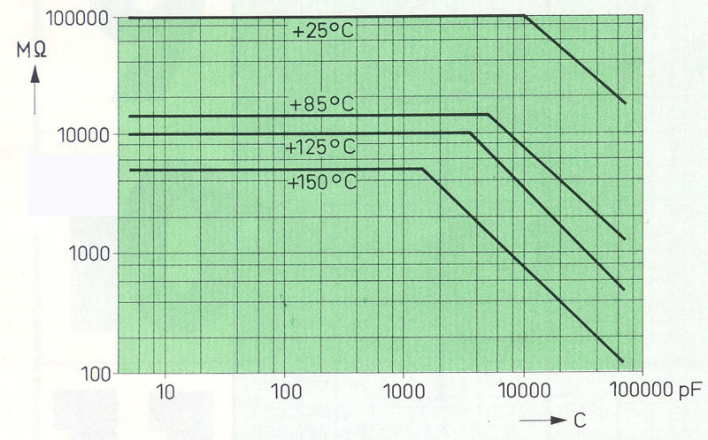
5.6 Insulation resistance at high temperatures
The insulation resistance at increased temperatures should meet the following minimum limits.

5.7 Rapid temperature change
Condition according to IEC 68-2-14, Na, 5 cycles with 30 min. duration, initial measuriement C and tan. Requirements: measuring of capacitance variation and loss factor should not rise above the following values:

5.8 Humidity, heat konstanz
Initial measurements: C, tan R, and Up. Conditions: IEC 68-2-3, ca respectively. DIN 40046, climate 40/93. Stress time duration according climate class. Requirements after 1 to 2 hours duration of recovery. c ± 0.5% or 0.5 pF, tan initial value, R: >= 25000 M, Up = 2 UN no interruption, without damage.
5.8.1 Humidity resistance
Conditions in accordance with MIL specifications. initial measurement: C, tan Rj, Up. MIL-STD-202, method 106
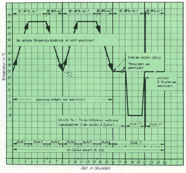
The samples run off a 24-hour cycle as shown in the diagram. MIL-C-5 configures 10 cycles, MIL-C-39001 configures 20 cycles. Requirements after 4 until 24 hours time recovery.

5.9 Temperature coefficient and capacitance drift
The capacitors are brought sucessive to the following temperatures. At all temperatures the capacitance is measured.
- (20 ± 2) ° C
- Lower junction temperature ± 3 ° C
- Intermediate temperature, if required
- (20 ± 2) ° C
- Intermediate temperature, if required
- Upper junction temperature ± 2 ° C
- (20 ± 2) ° C
For controlling a simplified procedure is allowed, eg. measurements according to item 4, 6 and 7, which covered the range between 20 ° C and upper junction temperature. According to the identification letters the following values must be kept.

5.10 Durability
Conditions: IEC 384-1/24. 21 test samples are loaded with 1.5 UN during 1000 h (or 2000 until 10000 h) at the upper juntion temperature. Requirements after 24 h ± 2 h time of recovery: Measurements: C, tan and Rj permissible changes depend on type, without damage. A falling out after 1000 h is tolerable.
6. General Information
Letters and numerical code as per MIL.
6.1 Capacity
The rating value is given in triple-digit numbers in pF. The first two digits indicate the numerical value, and the third number indicates the subsequent zeros:
12 pF = 120
120 pF = 121
1200 pF = 122
12000 pF = 123
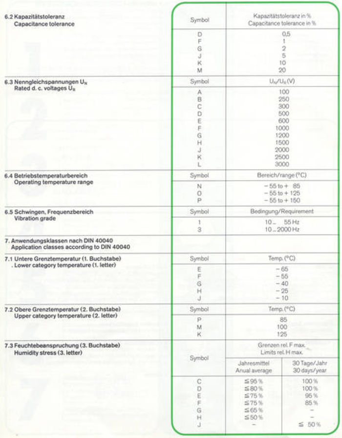
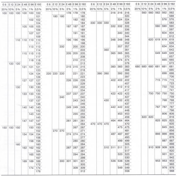
Ranges
